Board description
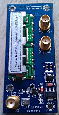
The board is designed to be a simple RF front end when using OpenBTS in the DCS (GSM1800) band with a RFX daugther board. One of the big advantages of using it is to reduce the crosstalk between RX & TX compared to using two antennas ( RX & TX ) next to each other. With it you have a single antenna port that you can connect to a good antenna with the gain and radiation pattern you want.
The board consists of :
-
A duplexer:
Raditek DUP-1710-1785M-1805-1880M-4415-3W-S-cc-j (datasheet)This allows to connect both the TX and the RX side to the same antenna without having the TX signal burning the RX stage. This particular one is a small ceramic duplexer featuring 48 dB of isolations for 3 dB of insertion loss.
-
A LNA:
RFMD RF3861 (datasheet)The LNA amplifies the weak signals received by the antenna. Altough the USRP does have plenty of gain, putting a LNA close to the antenna allows to compensate for loss you would have in cables, or in subsequent elements like the RX filter we have here. This particular model has a typical current of around 100 mA. It features a gain of around 14.5 dB for the DCS band with a noise figure < 1 dB.
-
A RX filter:
EPCOS B39172-B3832-U410 (datasheet)This passband filter specially designed for GSM BTS base stations provides additional filtering, eliminating signals out of the range of interest.
Simple tests
In this set of test, I used the USRP to generate a pure carrier at a known levels and various frequencies inside the GSM1800 band, both uplink and downlink, and measured the response through various paths.
All measurements in this section have been made using an Agilent E4406A, by taking the spectrum view and looking at the average amplitude at the center frequency.
LNA & RX-filter only
This is preliminary testing with just the LNA and RX filter. I didn't solder the duplexer on that test board and instead directly soldered a RG174 cable onto the pad. This allowed to inject a signal 'as-if' it came out of the RX port of the duplexer.
For each frequency, I tested at two different input power levels.
The results are presented in three columns:
- Direct : This is the power measured directly at the output of the USRP
- LNA+ RX-filter : This is the amplitude measured at the output of the modified test board
- Delta : Difference of amplitude, showing the effect the LNA+RX-filter had on the signal
| ARFCN | Frequency (MHz) |
Direct (dBm) |
LNA + RX-filter (dBm) |
Delta (dB) |
|---|---|---|---|---|
| Downlink | ||||
| 512 | 1710.2 | - 33.27 | - 23.05 | + 10.22 |
| - 2.75 | 7.33 | + 10.08 | ||
| 698 | 1747.4 | - 33.87 | - 21.90 | + 11.97 |
| - 3.30 | 8.56 | + 11.85 | ||
| 885 | 1784.8 | - 34.20 | - 24.61 | + 9.60 |
| - 3.65 | 5.77 | + 9.42 | ||
| Uplink | ||||
| 512 | 1805.4 | - 34.50 | - 38.10 | - 3.60 |
| - 4.01 | - 7.70 | - 3.69 | ||
| 698 | 1842.4 | - 35.10 | - 48.34 | - 13.24 |
| - 4.57 | - 17.86 | - 13.29 | ||
| 885 | 1879.8 | - 35.90 | - 56.73 | - 20.83 |
| - 5.39 | - 26.30 | - 20.91 | ||
Complete frontend
Theses two sets of tests are made with the front end completely assembled. They're made with a different board than the preliminary tests above tough.
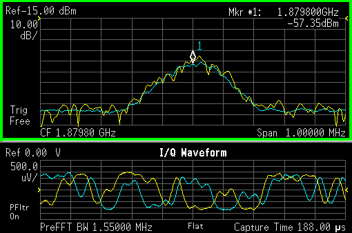
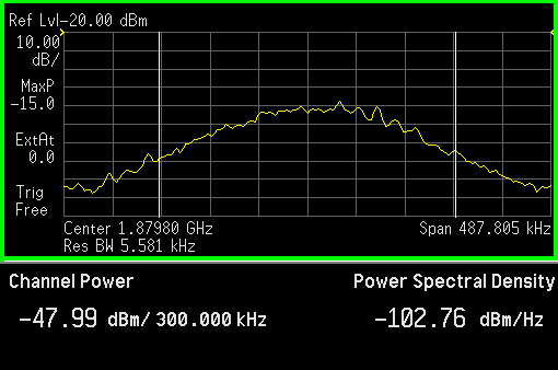
The following results are for testing the TX to RX cross-talk. A fixed carrier is generated at various points on the downlink band and sent to the TX port of the front end. Readings are then taken at the RX port, see what leaked through. The antenna port was connected to a VERT900 antenna during this test.
| ARFCN | Frequency (MHz) |
Input [TX port] (dBm) |
Output [RX port] (dBm) |
Delta (dB) |
|---|---|---|---|---|
| 512 | 1805.2 | - 4.5 | - 63.0 | - 58.5 |
| - 35.0 | - 93.0 | - 58.0 | ||
| 698 | 1842.4 | - 4.9 | - 72.0 | - 67.1 |
| - 35.5 | < - 100 | < - 64.5 | ||
| 885 | 1879.8 | - 5.7 | - 61.5 | - 55.8 |
| - 36.3 | - 92.0 | - 55.7 |
The following results are for testing the RX performance. A 'weak' carrier is generated in the uplink band and injected in the front end via the ANTenna port. This simulates a signal received from a phone. Readings are then taken on the RX port to see what the USRP would receive.
| ARFCN | Frequency (MHz) |
Input [ANT port] (dBm) |
Output [RX port] (dBm) |
Delta (dB) |
|---|---|---|---|---|
| 512 | 1710.2 | - 33.50 | - 22.05 | + 11.45 |
| 698 | 1747.4 | - 34.15 | - 24.30 | + 9.85 |
| 885 | 1784.8 | - 34.70 | - 25.90 | + 8.8 |
OpenBTS tests
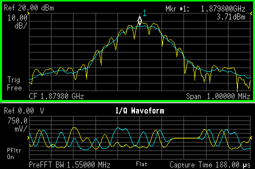
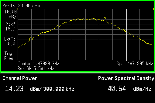
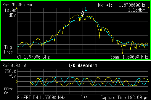
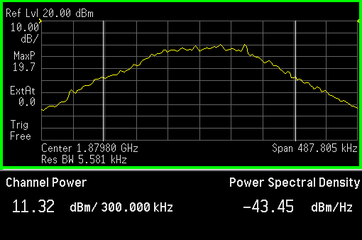
In these final tests, I ran a complete OpenBTS 2.6 release, running on ARFCN 885 with a 52MHz clock.
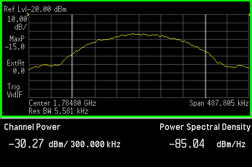
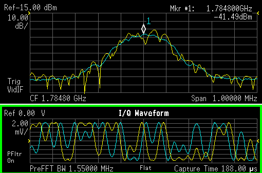
Note that to be able to view what the USRP receives, the front end RX port was connected, through a resistive power splitter to both the USRP RX2 port and the Agilen E4406A. This splitter incurred a 6.5 dB loss that you must take into account when interpretin all the mesurements below. Only the 'direct connection' measurements don't have this additional attenuation
Downlink
| USRP Source [Direct connection] | ||
|---|---|---|
|
|
|
| Antenna port | ||
|
|
|
| Crosstalk to RX port | ||
|
|
|
Uplink
Some measurement of uplink with a channel active. The phone was only 1 meter or so from the BTS during those tests
| Channel power |
|
|---|---|
| Spectrum |
|
| RF Envelope |
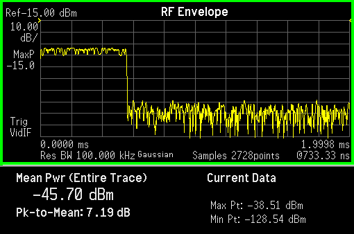
|
| OpenBTS channel infos |
OpenBTS> chans TN chan transaction UPFER RSSI TXPWR TXTA DNLEV DNBER TN type id pct dB dBm sym dBm pct 2 TCH/F 1804289383 0.00 0 6 0 -48 0.00 |
For comparaisons, here's some measurement on the uplink whith the phone at the edge of the cover zone
| RF Envelope |
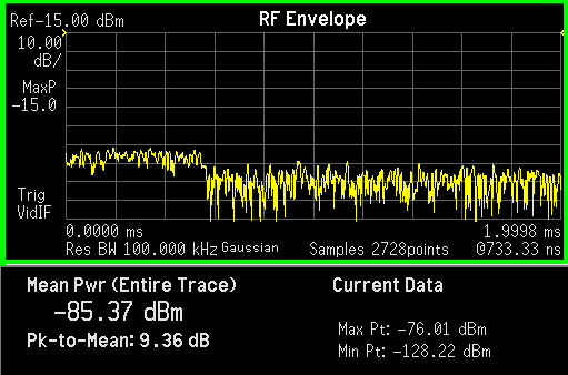
|
|---|---|
| OpenBTS channel infos |
OpenBTS> chans TN chan transaction UPFER RSSI TXPWR TXTA DNLEV DNBER TN type id pct dB dBm sym dBm pct 2 TCH/F 1804289386 0.00 -38 30 0 -98 0.00 |
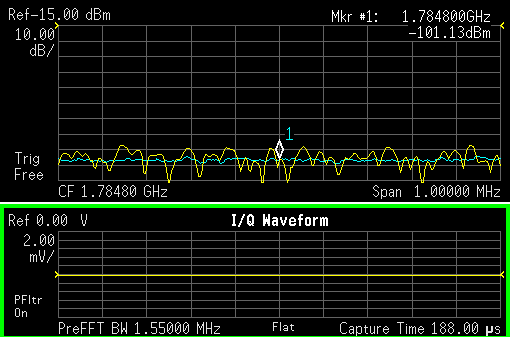
A concern that was also raised in the noise generated by the USRP in the uplink band even when its transmitting in the downlink band. The following shot shows that I can't see any trace of it.


 Maintained by Sylvain Munaut tnt >at< 246tNt >dot< com